Modern television distribution connects two worlds: compressed digital video and the radio frequency infrastructure that carries it to viewers. Between an encoder and a television, several technologies must cooperate to preserve picture quality, synchronize sound, identify channels, and deliver a stable signal. The phrase “H.264 / HEVC MPEG-TS to QAM” describes this connection, bringing advanced video compression into cable distribution systems. This workflow matters wherever operators want to distribute multiple television services over coaxial cable. Hotels, hospitals, residential buildings, campuses, and cable headends can all use it. However, successful deployment requires more than selecting a modulator. Engineers must understand which component compresses video, which organizes programs, and which creates the RF signal. This article explains those responsibilities and shows how they work together in a practical distribution chain.
1. Three Technologies, Three Different Jobs
H.264, also called AVC, and HEVC, also called H.265, are video compression standards. They reduce the data needed to represent moving pictures by exploiting spatial and temporal redundancy. Their output is a compressed video elementary stream, which still needs supporting transport and signaling before television receivers can use it.
MPEG Transport Stream, or MPEG-TS, provides that transport structure. It carries video, audio, timing information, and tables that describe the available programs. Despite its association with MPEG-2 Systems, it can carry newer video formats, including H.264 and HEVC. The container name does not mean that the video must use MPEG-2 compression.
Quadrature Amplitude Modulation, or QAM, operates at the transmission layer. It maps digital information onto combinations of carrier amplitude and phase, producing a signal suitable for cable delivery. These technologies therefore form complementary stages: compression makes video manageable, transport makes services interpretable, and modulation makes the multiplex transmissible over an RF channel.
2. Choosing Between H.264 and HEVC
H.264 remains a practical choice when receiver compatibility is the main priority. Many installed televisions and set top boxes support AVC, making it useful for HD channel distribution across mixed equipment fleets. However, support still depends on the selected profile, level, resolution, frame rate, and other encoding parameters.
HEVC offers greater compression efficiency and is particularly attractive when bandwidth is limited or higher resolutions are required. Its efficiency can allow operators to improve picture quality at a given bitrate or reduce bitrate while maintaining an acceptable viewing experience. Actual savings depend on content complexity, encoder quality, latency targets, and quality criteria; a universal percentage should never replace testing.
The receiver population should drive the decision. A television may support HEVC through a streaming application or USB playback without supporting the same format through its cable tuner. Before migration, test representative devices using the intended broadcast configuration. Include audio, subtitles, channel discovery, and sustained playback, because decoding one sample clip does not establish complete service compatibility.
3. How MPEG-TS Organizes Television Services
A conventional MPEG transport stream consists of fixed packets containing 188 bytes. Each packet includes a Packet Identifier, or PID, which lets receivers distinguish video, audio, signaling, and other components. Multiple programs can share one transport stream, allowing a single RF channel to carry several television services.
The Program Association Table identifies programs and points to their Program Map Tables. Each Program Map Table describes the elementary streams belonging to a program. Correct stream types and applicable descriptors help receivers recognize the codecs and associate the right video and audio components. DVB deployments also use service information to support functions such as service naming and network discovery.
Timing is equally important. Program Clock References support recovery of the program clock, while presentation and decoding timestamps govern when compressed content should be processed and displayed. Poor timing, missing packets, or incorrect tables can cause frozen pictures, unstable audio, or channels that appear in a scan but cannot play reliably, even when the RF signal looks healthy.
4. What “MPEG-TS to QAM” Actually Means
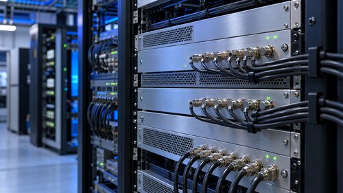
In a typical headend, a gateway or modulator receives MPEG-TS through an interface such as ASI or IP. It may accept a complete multiplex or select services from several inputs and remultiplex them into a new output stream. The device then applies the channel coding and modulation required by the selected cable standard.
This process does not inherently decode or recompress video. When the incoming codecs and parameters already match the receiver requirements, compressed streams can pass through the system without a video transcoding stage. That preserves the encoded picture and avoids the processing delay and generation loss associated with recompression.
Transcoding becomes necessary when an input exceeds receiver capabilities, uses an unsupported codec, or needs a lower bitrate or different resolution. Remultiplexing changes how programs and packets are assembled; transcoding changes the compressed media itself. Keeping these operations distinct helps operators choose appropriate hardware and diagnose problems at the correct stage of the distribution chain.
5. Understanding QAM Capacity and RF Tradeoffs
QAM modulation orders determine how many bits each symbol represents. For example, 64-QAM carries six bits per symbol, while 256-QAM carries eight. At the same symbol rate, the higher order can carry more data, but its constellation points are closer together, demanding better signal quality for reliable reception.
Cable standards must also be considered. European DVB-C and North American cable implementations do not use identical framing and channel coding arrangements. A useful transport bitrate therefore depends on the applicable standard, modulation order, symbol rate, and coding overhead. It should be calculated for the actual output configuration rather than inferred from the QAM label alone.
For an illustrative DVB-C configuration, 256-QAM at 6.9 million symbols per second produces 55.2 megabits per second before Reed–Solomon overhead. Applying the 188/204 transport packet ratio gives approximately 50.9 megabits per second for the transport stream. That capacity includes packet headers, signaling, audio, and other carried data; it is not entirely available for video payload.
6. Building a Stable Multiplex
Capacity planning starts with the complete services, not just their video bitrates. Audio tracks, subtitles, service tables, and transport overhead all consume bandwidth. Variable bitrate video also introduces peaks that must fit within the multiplex capacity or be managed by appropriate buffering and multiplexing mechanisms.
For example, six services with video averaging five megabits per second each represent thirty megabits per second of average video traffic. That calculation alone does not prove that the services fit safely. Operators must account for the other components and assess whether simultaneous bitrate peaks could overload the output.
A fixed rate QAM output needs a transport stream matched to its configured capacity. Null packets can fill unused transport capacity; supported rate adaptation or remultiplexing functions manage input differences. Buffers can absorb short bursts but cannot solve sustained overload. Statistical multiplexing can allocate video bitrate dynamically among cooperating encoders, although independently encoded inputs do not automatically become statistically coordinated merely by sharing one output multiplex.
7. Commissioning and Troubleshooting the Complete Chain
Commissioning should examine both transport integrity and RF performance. At the stream level, check continuity counters, program tables, codec signaling, timing behavior, and bitrate stability. For IP inputs, verify multicast configuration where applicable and assess packet loss, jitter, and network congestion before assuming that the modulator is responsible.
At the RF level, measure output power, Modulation Error Ratio, and relevant Bit Error Ratio indicators. Inspect the distribution network for excessive attenuation, poor connectors, ingress, amplifier distortion, and unbalanced channel levels. Measurements should cover remote outlets as well as the headend, since a clean transmitter output does not guarantee a clean signal at every television.
Symptoms help narrow the search. If multiple services on one carrier fail together, investigate shared transport or RF conditions. If only one service fails, inspect its tables, timing, codec parameters, and source integrity. A channel with sound but no picture may indicate video incompatibility. These patterns guide investigation, but measurements and controlled comparisons should confirm the diagnosis.
8. Planning a Practical Migration
An effective upgrade begins with an inventory of receivers, sources, and available RF capacity. Operators can introduce HEVC where devices support it while retaining H.264 services for older equipment. Because a transport multiplex can contain different supported video codecs, migration does not necessarily require replacing every service at once.
Pilot testing should include demanding scenes, channel changes, source interruptions, and recovery after network faults. Document working parameters and monitor the system after deployment. The result is a controlled bridge between efficient video compression and established cable infrastructure: one that delivers clear pictures today while creating room for future services and changing viewer expectations across the entire network.
The strongest designs also make everyday operation straightforward. Clear service names, consistent channel numbering, accessible monitoring, and documented recovery procedures reduce support effort. Where continuity matters, redundant sources and power arrangements should be evaluated against operational needs. Equipment selection should follow measured requirements rather than headline codec support. By treating compression, transport, and RF delivery as separate responsibilities within one system, operators can expand capacity without losing sight of the viewing experience at every connected screen.